As we’ve seen, simple objects such as service trenches and fences can be quickly created. But what if you have something more complex, such as a guard rail.
BIM=>Trimesh=>Create=>Trimesh BIM Objects Create/Edit
If you don’t already have an editable file in the Working Folder, please see here: 12dwiki.com.au/trimesh-bim-objects-create/
Abbreviations
The following abbreviations will be used throughout this page;
- LMB – Left Mouse Button
- RMB – Right Mouse Button
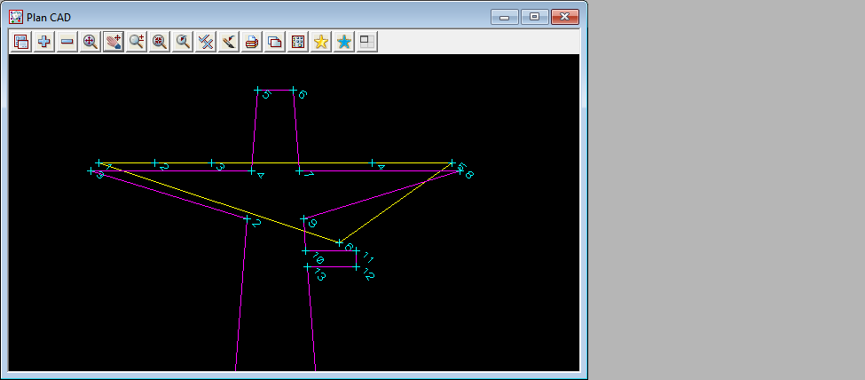
Below is a crude layout for a basic pole and cable layout. The magenta string will be used to create the poles, and the yellow string defines the location for the cables.
- When using Path for a vertex object, the shape will be extruded along the path and an object placed at each vertex.
- When using Path for segment objects, the shape will be extruded from each vertex on the path and an object placed parallel to the segment.

<Create New> to add a new Vertex-Segment Type;
- Name: Power
then select <Working>.
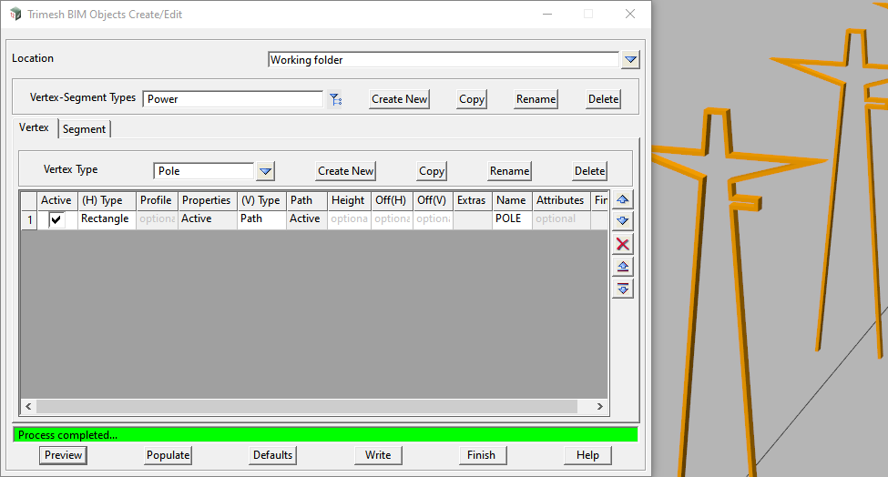
On the Vertex tab, <Create New> to add a Vertex Type: Pole
On Row 1, enter the following values;
- Active: On
- (H) Type: Rectangle
- LMB in the Properties cell and enter;
- Width: 0.15
- Length: 0.05
- Colour: orange
- Rotation Perpendicular: On
- Then <Set> to apply the changes, and <Finish>.
- (V) Type: Path
- Path:
- Select the path in the CAD view and <Set>.
- Name: POLE
<Preview> and <Write> the file.

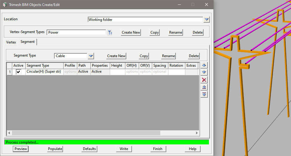
On the Segment tab, <Create New> to add a Segment Type: Cable
On Row 1, enter the following values;
- Active: On
- Segment Type: Circular (H) (Super str)
- Path:
- Select the path in the CAD view and <Set>.
- LMB in the Properties cell and enter;
- Dia: 0.05
- Colour: magenta
- Pipe/Culvert Justify: Center
- Then <Set> to apply the changes, and <Finish>.
- Name: CABLE
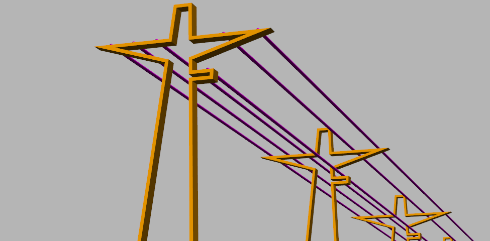
<Preview> and <Write> the file. A segment part will be created at each vertex on the path.

To apply the BIM Object, please see here: 12dwiki.com.au/trimesh-bim-objects-apply/
