Velocity Calculation
At EACH TIME STEP the Dynamic Drainage Engine performs the following calculations for each node and conduit in the network:
Velocity at Upstream and Downstream ends of the Conduit
- The water surface level at each node is calculated.
This is done by determining the volume of water stored at each node at that time step, and dividing by the node area (size of the pit)
The volume of water stored at the node is in turn calculated by determining the inflows and outflows at the node. - For each link, the upstream and downstream water levels at the respective nodes are used to calculate the upstream and downstream depths in the conduit.
The difference between the upstream and downstream depths is used to calculate the flow in the conduit. - The depth of flow at each end of the conduit, and the shape of the conduit are used to determine the cross section area of the flow at each end of the conduit.
- The velocity at each end of the conduit is calculculated as the flow/area.
Velocity Mid-Channel on Conduit
- The results for water levels described above are averaged to determine the depth of flow mid-channel.
- The mid-channel depth gives a mid-channel cross-sectional area of flow, and the mid-channel velocity is calculated as the flow/area.
Under open channel conditions (part-full pipe flow) , the mid-channel depth is the average of the upstream and downstream depths.
The velocity will be different at the upstream, mid-conduit, and downstream ends of the conduit.
Under full flow conditions, the velocity at mid-conduit and at both ends will be the same.
Results and Reporting
The maximum velocity upstream, downstream and mid-conduit are stored at attributes on the link:
Upstream velocity: calculated pipe max velocity us
Mid-conduit velocity: calculated pipe max velocity
Downstream velocity: calculated pipe max velocity ds
The results graph of velocity for the link shows the mid-conduit velocity.
Comment
The velocity calculations for pipes at steep grades are sensitive to tailwater conditions (or to the water levels in the downstream node).
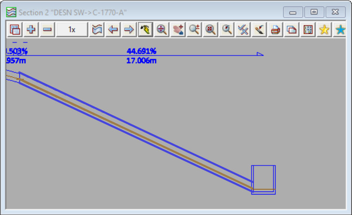
In the first screenshot below the tailwater level (the downstream water level) for the steep link is determined by 12d Model (using critical depth and normal depth equations).
The downstream water level is low, and as a result the water level at the mid point of the conduit is low – the pipe is approx quarter full.
The low water level at midpoint leads to a low cross section area of the flow in the pipe, and a hence a high velocity.
The calculated maximum velocity for this link shown in this configuration is 9.05m/s
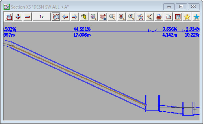
In the second screenshot the nodes and links downstream of the steep link result in the downstream water level for that link to be high.
The downstream water level is high, and as a result the water level at the mid point of the conduit is high – the pipe is approx half full.
The high water level at mid point leads to a high cross section area of flow in the pipe and hence a (comparitively) low velocity.
The calculated maximum velocity for the link shown in this configuration is 5.83m/s

