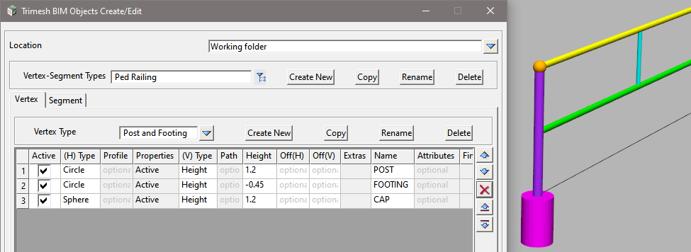
Easily create objects such as fences, guard rails, bus shelters, bridges, etc. Or copy and edit any of the supplied objects.
To apply the BIM Objects, see here: 12dwiki.com.au/trimesh-bim-objects-apply
BIM=>Trimesh=>Create=>Trimesh BIM Objects Create/Edit
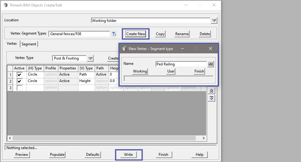
Before you can create new objects, you need to create an editable file in the Working Folder. This can be done by copying an existing object.
Select <Copy> and enter the name of an existing object, such as General fences/F08, then select <Working>

Abbreviations
The following abbreviations will be used throughout this page;
- LMB – Left Mouse Button
- RMB – Right Mouse Button
As a BIM Object can be comprised of multiple parts, each Vertex-Segment Type can be a complete entity. For example you can have an object (Type) called Fence, and the multiple parts (footings, posts, railings) are stored under Vertex and Segment. The parts go together to create the object.
<Create New> to add a new Vertex-Segment Type and enter the Name: Ped Railing, then select <Working>.
<Write> to save the file.
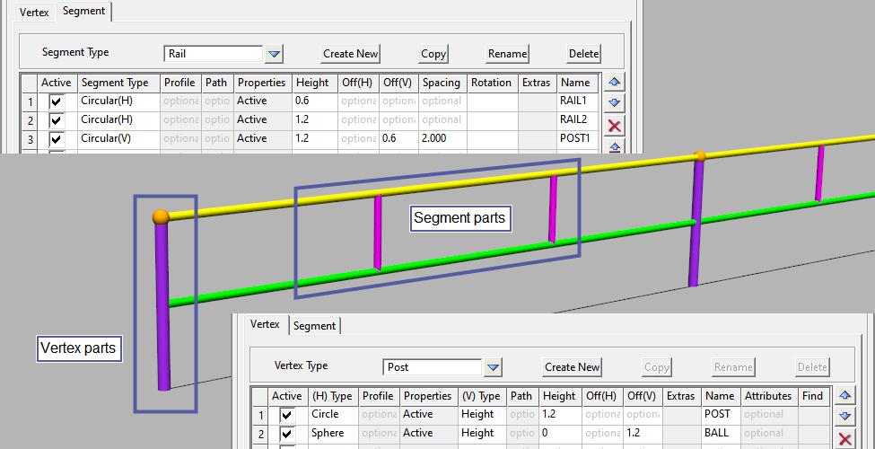
Vertex v’s Segment
As the tab headings suggest, parts created under Vertex will only be placed at a vertex. Likewise parts created under Segment will be placed along a segment.
Segment parts do not have to be parallel to the string segment. You can place vertical (or any angle) parts along a segment at a defined spacing.
Using a simple pedestrian railing as an example, the corner posts will be vertex parts, whilst the railing AND intermediate posts will be segment parts.
Vertex
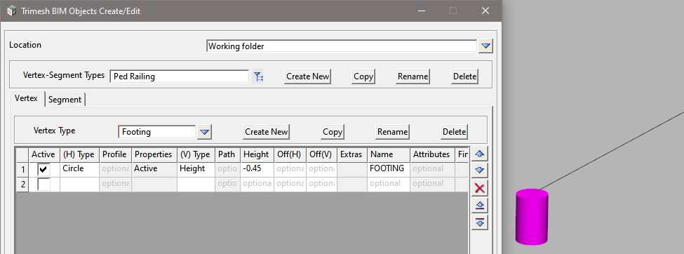
On the Vertex tab, select <Create New> and add a Vertex Type: Footing, then <Set> and <Finish> .
In the grid, enter the following values;
- Active: On
- (H) Type
- RMB in the cell to bring up the available options,
- Select: Circle
- LMB in the Properties cell,
- As a minimum you need to enter;
- Diameter: 0.3
- Colour: magenta
- Then <Set> to apply the changes, and <Finish>.
- RMB in the (V) Type cell and select: Height
- Height: -0.45 (negative for down)
- Heights are measured relative to an insert point of Z = 0
- Name: FOOTING
<Preview> to see how it looks. And remember to <Write> the file.
<Create New> to add another Vertex Type: Post
In the grid, enter the following values;
- Active: On
- (H) Type
- RMB in the cell and select: Circle
- LMB in the Properties cell,
- As a minimum you need to enter;
- Diameter: 0.09
- Colour: purple
- Then <Set> to apply the changes, and <Finish>.
- RMB in the (V) Type cell and select: Height
- Height: 1.2
- Name: POST
<Preview> to see how it looks, and <Write> the file.

Notice that the <Preview> only shows the currently selected Vertex and Segment parts.
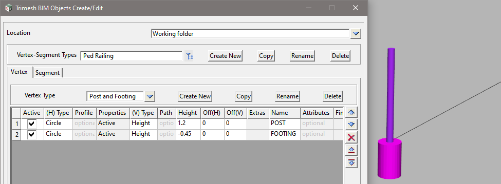
<Copy> and enter the Name: Post and Footing
<Set> and then <Finish>
<Preview> and remember to <Write>

Copy across the previous footing details;
Change to the Vertex Type: Footing
- RMB on Row 1 and select Copy

Change to the Vertex Type: Post and Footing
- RMB on Row 2 and select Paste

The Properties don’t copy across, so you will need to;
- LMB in the Properties cell and set,
- Diameter: 0.09
- Colour: purple
- Then <Set> to apply the changes, and <Finish>.
<Preview> and then <Write>
By combining the post and footing into a single part, we now see both in the preview.
Segment
Go to the Segment tab.
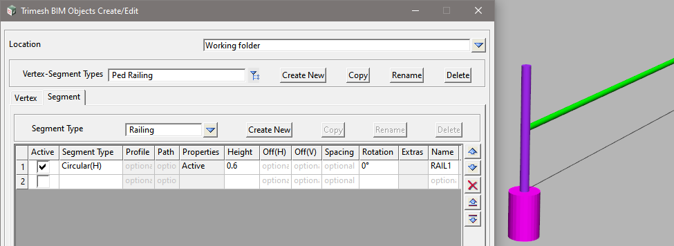
<Create New> to add a Segment Type: Railing to create the railing.
In the grid, enter the following values;
- Active: On
- Segment Type
- RMB in the cell and select: Circular (H)
Note that most types have (H) and (V), these are for Horizontal and Vertical.
- LMB in the Properties cell and enter;
- Diameter: 0.06
- Colour: green_240
- Pipe/Culvert Justify: Center
- Then <Set> to apply the changes, and <Finish>.
- Height: 0.6
- Rotation: 0
- The rotation is relative to the direction of the segment.
- Name: RAIL1
<Preview> and remember to <Write> the file.
Next add the top rail.
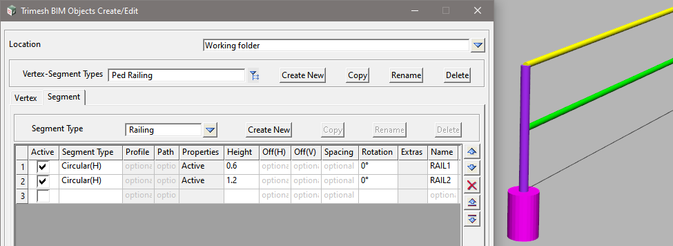
In Row 2 of the grid, enter the following values;
- Active: On
- Segment Type
- RMB in the cell and select: Circular (H)
- LMB in the Properties cell and enter;
- Diameter: 0.06
- Colour: yellow
- Pipe/Culvert Justify: Center
- Then <Set> to apply the changes, and <Finish>.
- Height: 1.2
- Rotation: 0
- Name: RAIL2
<Preview> and then <Write> the file.
Create some intermediate posts. This time we will use a vertical part.
In Row 3 of the grid, enter the following values;
- Active: On
- Segment Type
- RMB in the cell and select: Circular (V)
- LMB in the Properties cell and enter;
- Diameter: 0.045
- Colour: cyan_240
- Pipe/Culvert Justify: Center
- Then <Set> to apply the changes, and <Finish>.
- Height: 1.2
- Off(V): 0.6
- This will raise the base of the post 0.6 from the insert point.
- Spacing: 2
- This is the spacing along the segment, between vertices.
- Rotation: 0
- Name: POST2
<Preview> the fence and <Write> the file.

To finish off, we’ll add a cap to the vertex posts.
Go to the Vertex tab, and add another row. In the grid, enter the following values;
- Active: On
- (H) Type
- RMB in the cell and select: Sphere
- LMB in the Properties cell and enter;
- Diameter: 0.12
- Colour: orange
- Then <Set> to apply the changes, and <Finish>.
- RMB in the (V) Type cell and select: Height
- Height: 1.2
- Name: CAP
<Preview> and <Write> the file.
