12d Model creates a lot of attributes, and not all of them are welcome in your Federated BIM Model.
This post describes the preparation of an attribute manipulator file that can be used to manage the attributes sent to the Federated Model.
It can also be used to prepare attributes for export to an asset management package (COBIE is the example used here).
The results of using this Attribute Manipulator File during export of an IFC file to Federated BIM model is shown in Attribute Management for Digital Engineering
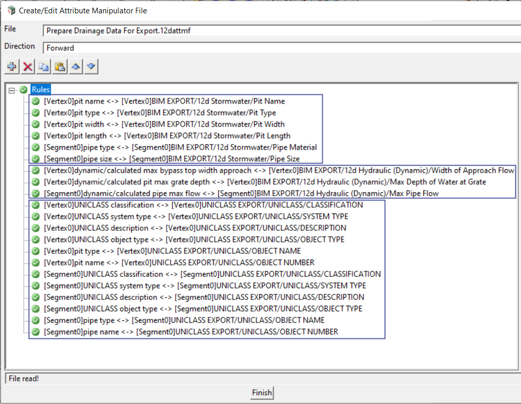
The screenshot below shows an example attribute manipulator file.
It has Manipulator Rules to process the attributes for three different purposes:
- Information about the physical layout of the stormwater network
- Hydraulic information from the dynamic analysis
- Data that will be processed for export to COBIE
Each of these is described below.
Note that it would more usual to have three separate Attribute Manipulator files to process this data, the rules are all in one file for simplicity on this post.
The Attribute Manipulator file used in this post can be downloaded

The first set of Rules is described, using the ‘Pit Name’ rule as an example.
These Rules are used to prepare data about the physical layout of the Stormwater Network for export to a Federated Model.
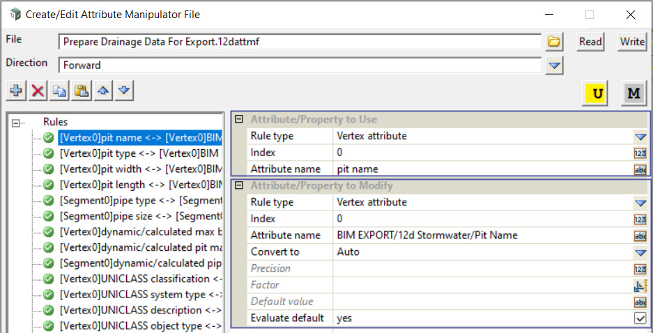
In the screen shot the ‘Pit Name’ rule is highlighted.
This rule will take the value of the ‘pit name’ attribute on an Inlet (pit) and create a new attribute (Pit Name) in a nested structure of Attribute Groups
The first part of the Rule (the ‘Attribute / Property to Use’) says:
The ‘Rule type’ is ‘Vertex attribute’.
In the case of a Water string, the vertices are Stormwater Inlets (Pits), so this says ‘use an attribute from an Inlet’
The ‘Index’ is zero. The ‘Index’ indicates which Inlet should be used (1 would be the first inlet in the drainage line, 2 the second inlet and so on).
In this case, setting it to zero means that all pits in the line will be used.
The ‘Attribute Name’ to be used is ‘pit name’. This is the unique identifier for the Inlet, typically ‘A-4’ (for Inlet #4 in line A).
The ‘Attribute/Property to Use’ can be summarised ‘Find the ‘pit name’ attribute for each of the pits’
The second part of the Rule (the ‘Attribute/Property to Modify’) says:
The ‘Rule type’ is ‘Vertex attribute’.
The Rule will create anew attribute on the Vertex
The ‘Index’ is zero. This setting (combined with the Index setting of zero on the ‘Attribute/Property to Use’) will cause the value of the ‘pit name’ attribute to be put back (as a new attribute) onto the same pit that it came from.
The ‘Attribute Name’ is the name of the new vertex attribute that will be created.
In this case the new attribute will be ‘Pit Name’ (note the capitalisation).
The important thing is that the new attribute will be stored in an attribute Group ’12d Stormwater’, which in turn will be stored in an attribute Group ‘BIM EXPORT’.
The ‘Attribute/Property to Modify’ can be summarised: ‘Store the value that was found in ‘Attribute/Property to Use’ (ie, the pit name of A/4), and store it in a new attribute ‘Pit Name’, and arrange that attribute is a nested arrangement of attribute groups’.

The second set of Rules is described, using the ‘calculated pipe flow’ rule as an example.
These Rules are used to prepare data about the Hydraulic Analysis Results for export to a Federated Model.
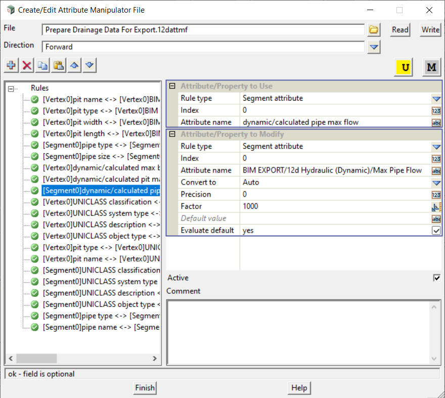
In the screen shot the ‘calculated pipe flow’ rule is highlighted.
This rule will take the value of the ‘pit name’ attribute on a pipe and create a new attribute (Max Pipe Flow) in a nested structure of Attribute Groups
The first part of the Rule (the ‘Attribute / Property to Use’) says:
The ‘Rule type’ is ‘Segment attribute’.
In the case of a Water string, the segments are links (pipes), so this says ‘use an attribute from a pipe’
The ‘Index’ is zero. The ‘Index’ indicates which link should be used (1 would be the first link in the drainage line, 2 the second link and so on).
In this case, setting it to zero means that all links in the line will be used.
The ‘Attribute Name’ to be used is ‘calculated pipe flow’,and this attribute is found in the ‘dynamic’ attribute group.
This attribute is storing one of the results of 12d Model’s ‘Dynamic Hydraulic Analysis’
The ‘Attribute/Property to Use’ can be summarised ‘Find the ‘pipeflow’ attribute for each of the pipes’
The second part of the Rule (the ‘Attribute/Property to Modify’) says:
The ‘Rule type’ is ‘Segment attribute’.
The Rule will create a new attribute on the Segment
The ‘Index’ is zero. This setting (combined with the Index setting of zero on the ‘Attribute/Property to Use’) will cause the value of the ‘calculated pipe flow’ attribute to be put back (as a new attribute) onto the same pipe that it came from.
The ‘Attribute Name’ is the name of the new segment attribute that will be created.
In this case the new attribute will be ‘Max Pipe Flow’ (note that the name of the new attribute is different).
The important thing is that the new attribute will be stored in an attribute Group ’12d Hydraulic (Dynamic)’, which in turn will be stored in an attribute Group ‘BIM EXPORT’.
The ‘Attribute/Property to Modify’ can be summarised: ‘Store the value that was found in ‘Attribute/Property to Use’ (ie, flow in the pipe), and store it in a new attribute ‘Max Pipe Flow’, and arrange that new attribute is a nested arrangement of attribute groups’.
