Headwalls are created quickly and easily in 12d Model.
In 12d Model 12 the command is Design=>Drainage/Sewer=>Create=>Create Culvert Headwalls
In 12d Model 14 the command is Water=>Water String=>Create=>Create Culvert Headwalls
- The Node Type MUST start with (uppercase) ‘HW.’ You can use the Headwall types that are shipped with 12d Model (ie HW in and HW out), or you can define your own sizes in the drainage.4d file (eg HW 450 – for a 450mm diameter pipe).
- In most cases the headwall will be either the first node on the pipe or the last node on the string (or both).
If the headwall is not the first or last node on the string, then both connected links at the node are checked for a top width (or a non-circular or non-rectangular shape).
If the top width (or shape check) is found for a link then that the link is a channel. Channel don’t get headwalls, so the other link is assumed to be the culvert and gets the headwall. - Standard Headwalls are available in two groups, either to NSW RMS requirements, or to standard Rocla (NSW) sizes. If either of these are suitable for your project, then no special entries are needed in the drainage.4d file
- The Inlet node MUST have the Ku value set to a culvert inlet – this is usually ‘Ku – Culvert Inlet – Generic (101 or 201)‘. If this is not set, the headwall will face the wrong way or will not be created.
- At present only headwalls square to the culvert are created. There is no consideration of skewed embankments.
- A trimesh (solid) is created to model the headwall. Strings are also created around the top of the wall – these are useful for the highway designer and allow the embankment to be adjusted to match the headwall

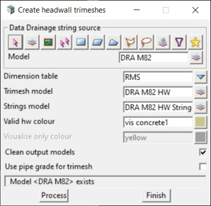
The ‘Drainage Data string source’ are the Water strings that are to get Headwalls. In this case a model has be chosen ‘DRA M82’
Dimension Table contains dimensions for either of RMS or Rocla NSW. These built-in sizes are used if the dimensions of the headwall have not been defined (see below).
Trimesh model is the model that will contain the new Headwalls
Strings model is the model that will contain strings at the back and edge of the Headwall, for use by the Highway Designer
How it Works
Headwall sizes are defined in one of three ways:
- Automatically, using one of the two tables of headwall sizes that are built into the routine.
The two tables of headwall sizes are for Rocla NSW and RMS NSW.
The tables cover pipe sizes from 375 mm to 1800 mm and from one to four barrels.
If your pipe sizes are in this range and you want NSW Rocla or RMS NSW size headwalls then then you have very little work to do.
If your pipe sizes fall outside this range, or you are not in NSW, or you are specifying Box Culverts, then you have a little work to do setting up the drainage.4d file - By setting attributes on the water string node. The easiest way to do this is by adding the attributes to an entry in the drainage.4d file.
This means that each different size of headwall will be stored separately in the drainage.4d file.
If you don’t want to create lots of different headwall types in the drainage.4d file, the attributes can be added manually using Strings=>Properties=>Attributes - Combination of 1 & 2, where some attributes may be set in the drainage.4d, and some taken from the table
Headwall Tables
Two tables of headwalls are builtin to the routine
- RMS (NSW Road & Maritime Services)
These are substantial structures with a cut off wall below the apron, typically used on highway projects.
The routine will automatically select the correct headwall from the table, based on the pipe size, for pipes up to - Rocla NSW
These are pre-cast headwalls. They are smaller structures, and typically used on land development projects.
Details of the headwalls are given here Headwall_Product_Details_(NSW_ACT)
The way that headwall sizes are defined in 12d Model is based on the sketches in this document.
Headwall Attributes
The most common way to set the node attributes (and hence set the headwall dimensions) is to defined them in the drainage.4d file.
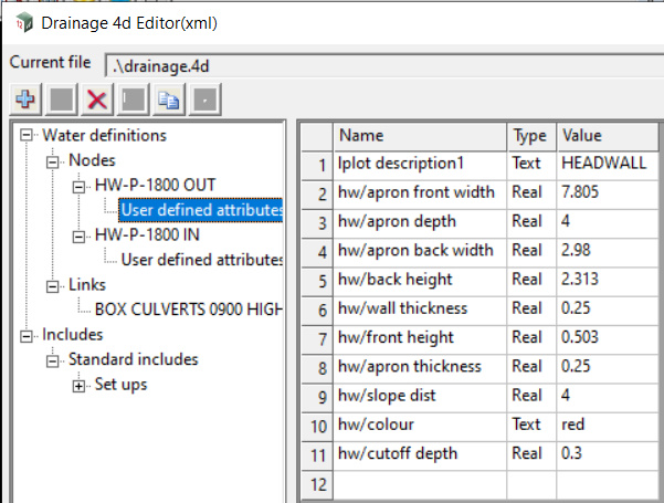
An example is given below showing a node in the drainage.4d file that has attributes.
Note that the attributes MUST go into an attribute group ‘hw\’
Examples drainage.4d files can be downloaded from this link for pipe headwalls and culvert headwalls
An example of the entries in the drainage.4d file is shown
In this example the headwall is for an 1800mm diameter pipe.
The file has two entries, one for inlet and one for outlet.
These are identical, except that the Ku method for the ‘Inlet’ have been set to ‘Ku – Culvert Inlet – Generic (101 or 201)’
When the HW-P-1800-OUT node type is chosen, and ‘Set Node Details’ is pressed, the Headwall attributes are created on the node, and will be used when the headwall is created.
In the example all 10 attributes have been set in the drainage.4d file, and none will be taken from the table

Combination of Table and Headwall Attributes
In most cases Designers will use either the predefined headwalls (Rocla or RMS) or will define headwall sizes in the drainage.4d file.
It is possible to use a combination of both, an example is the creation of the cut off wall at the front of the headwall.
If the cut off wall depth is not defined in the drainage.4d file, then the value is taken from the tables.
The RMS tables include a cut off wall depth, the Rocla tables do not.
So if a Headwall node type is chosen (where cut off depth is omitted) , then choosing the RMS table will create a cut off wall, and choosing the Rocla table will not.
Headwall Colour
The colour of the headwall is used to set the texture on the trimesh.
The colour can be set in three places, and (in order of precedence) these are:
- attribute colour – as set in the drainage.4d file
- panel colour – the panel colour of ‘vis_concrete’ shown above is optional, this field can be left blank on the panel.
- node colour – the colour of the node can be set in the WNE for each node, and if colour is not defined in the drainage.4d, and is not set in the panel, then the node colour will be used.
Multi Barrel Culverts – Pipe Separation
The built in tables of headwall sizes include separation for pipes with diameter between 375mm and 1800mm. If the pipes are in this range, then the separation from the table will be used
As the separation is between the outside of the pipes and the internal dimensions are used for the headwall holes, the separation is increased by the left + right thicknesses.
If no separation is found, then 300mm is used.
Headwall Angle and Elevation
- The node symbol angle controls the rotation of the headwall. If the headwall is the first node on the string it is rotated 180 degrees.
- The node sump level is used to set the top of apron elev.