This tool is used to create a CAD Point, located in the middle of two selected positions.
The video below will show how to create a CAD Point at the Mid-Point of two selected .
Or continue down the page to see the CAD Mid-Point create options.
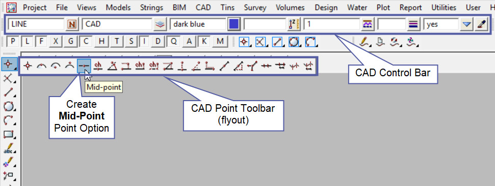
This CAD Point Mid-Point option is found on the CAD Point Toolbar, and is the 5th option when the toolbar files out.
Or from the menu, Use: CAD => Point => Mid-Point

CAD Control Bar Options
The Point is created and placed using the details from the CAD Control Bar, these include,
String Name, Model, Colour, Z – Value, Linestyle, Weight and Tinable.
If you would like to learn more about the CAD Control Bar and how to utilise it,
Visit this post: CAD Control Bar – How to Utilise It
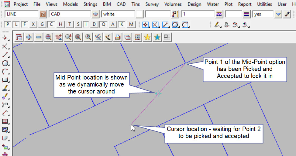
To create a point at the Mid-Point, two selected positions need to be picked and accepted for the Mid-Point to be created.
Note: Turn the model onto the screen if the point is not shown.
First select the first position and accept it. As the cursor is moved away from the first position the green line will show a proposed mid-point, basically waiting for a second position to be selected.

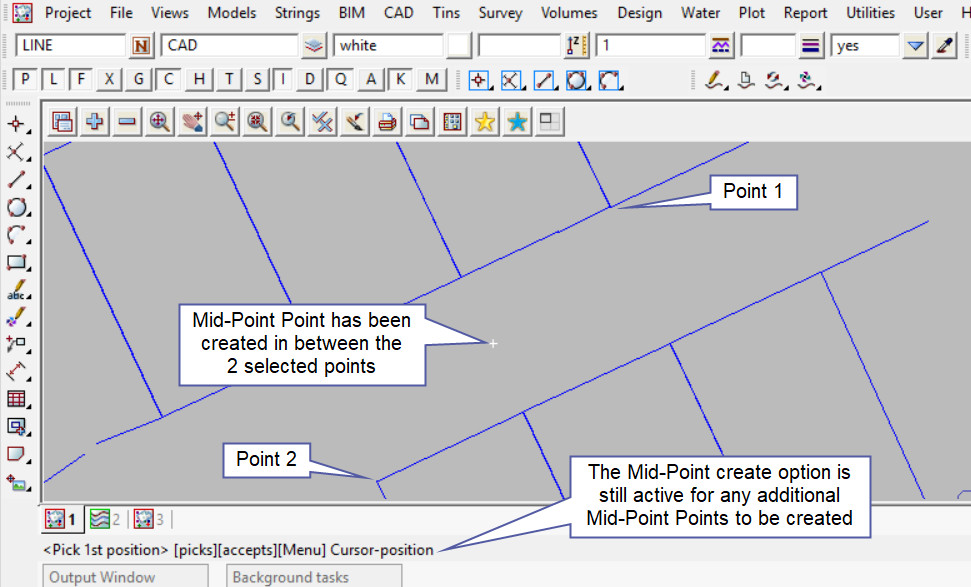
Pick and Accept on the second position for 12d Model to calculate the Mid-Point between the two positions.
Note: If a second point is to be created the option is still active in the project until another option is selected, or it is cancelled. The user can select the next string and use the option again.

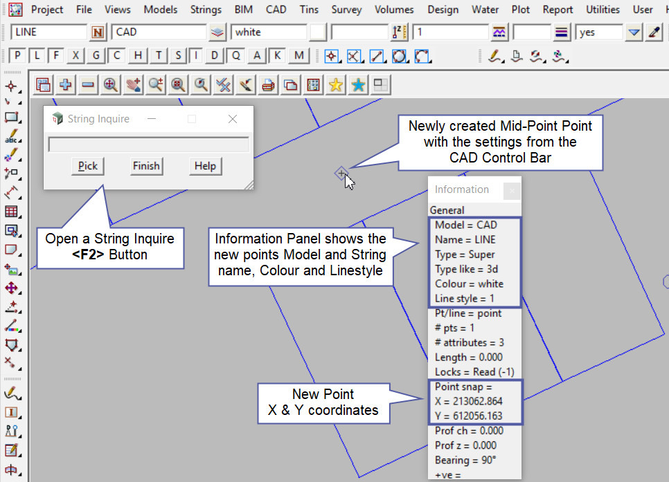
Use a String Inquire to check the details of the new point.
