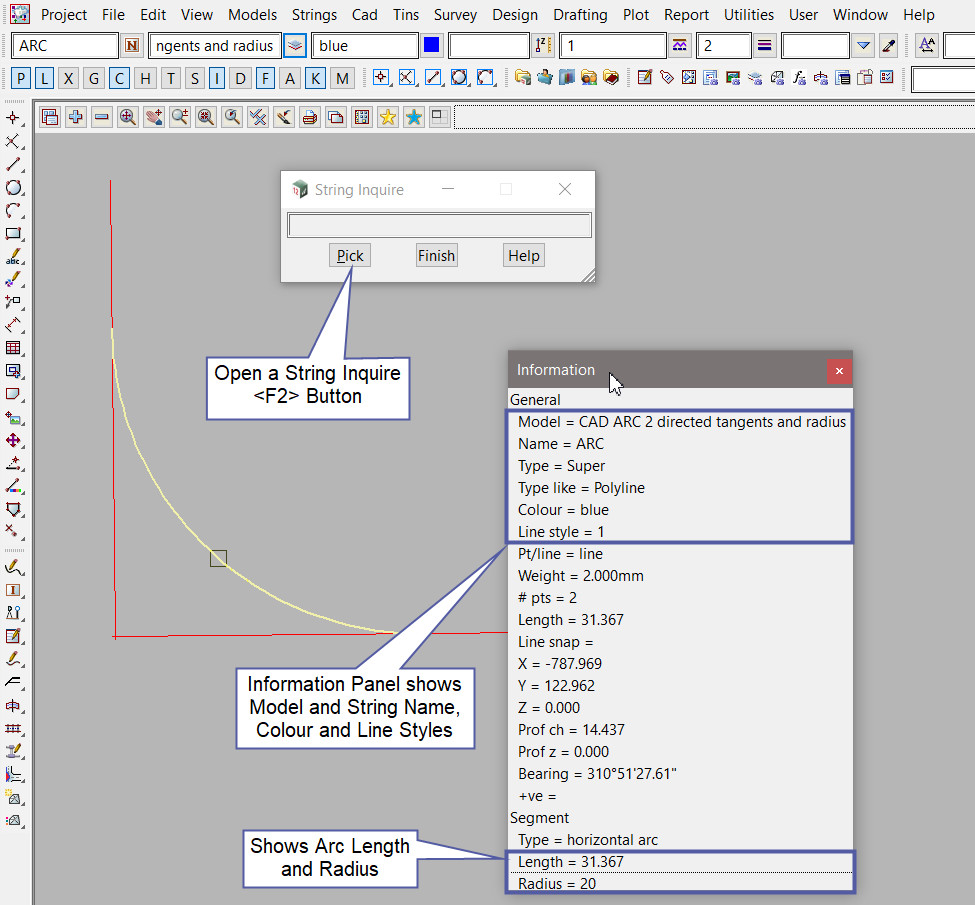
This tool is used to create a CAD Arc, using 2 directed tangents and radius.
The video below will show how to create a CAD Arc using 2 directed tangents and radius method.
Or continue down the page to see the CAD Arc 2 directed tangents and radius create option.
This CAD Arc 2 Directed Tangents and Radius option is found on the CAD Arc Toolbar, and is the 5th option when the toolbar files out.
Or from the menu, Use: CAD => Arc => 2 Directed Tangents and Radius
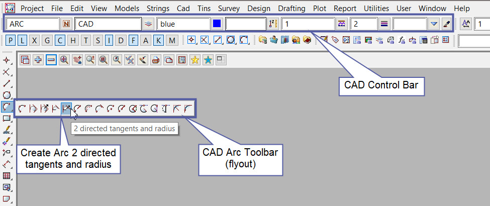
CAD Control Bar Options
The Arc is created and placed using the details from the CAD Control Bar, these include,
String Name, Model, Colour, Z – Value, Linestyle, Weight and Tinable.
If you would like to learn more about the CAD Control Bar and how to utilise it,
Visit this post: CAD Control Bar – How to Utilise It
Pick and Accept on the first tangent of a string segment with direction.
Note: Arc and Circles in 12d Model can be both clockwise and anti-clockwise in direction.
Clockwise arc/circles are entered into a panel with a positive (+) radius.
Anti-Clockwise arc/circles are entered into a panel with a negative (-) radius.
Please check the direction of the arc/circle to be created and use pick with direction if required.
If you would like to learn more about Picking with Direction and how to utilise it,
Visit this post: Picking with Direction
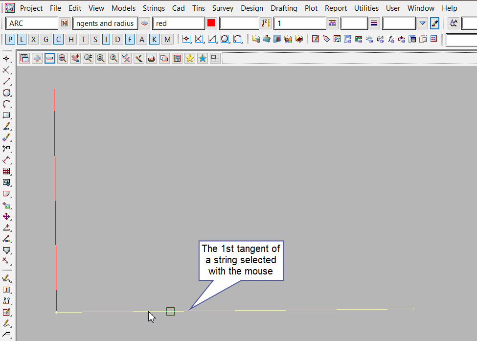
Pick and Accept the second tangent of a string segment with direction.
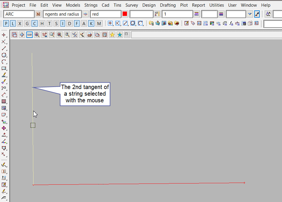
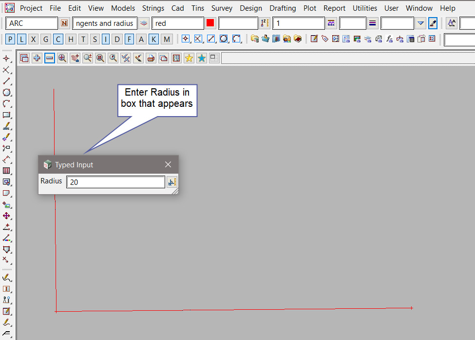
Type in the Radius for the arc, then hit the <Enter> key.
Remember the direction that the arc will be created, clockwise arc = positive radius, and an anti-clockwise arc = negative radius.
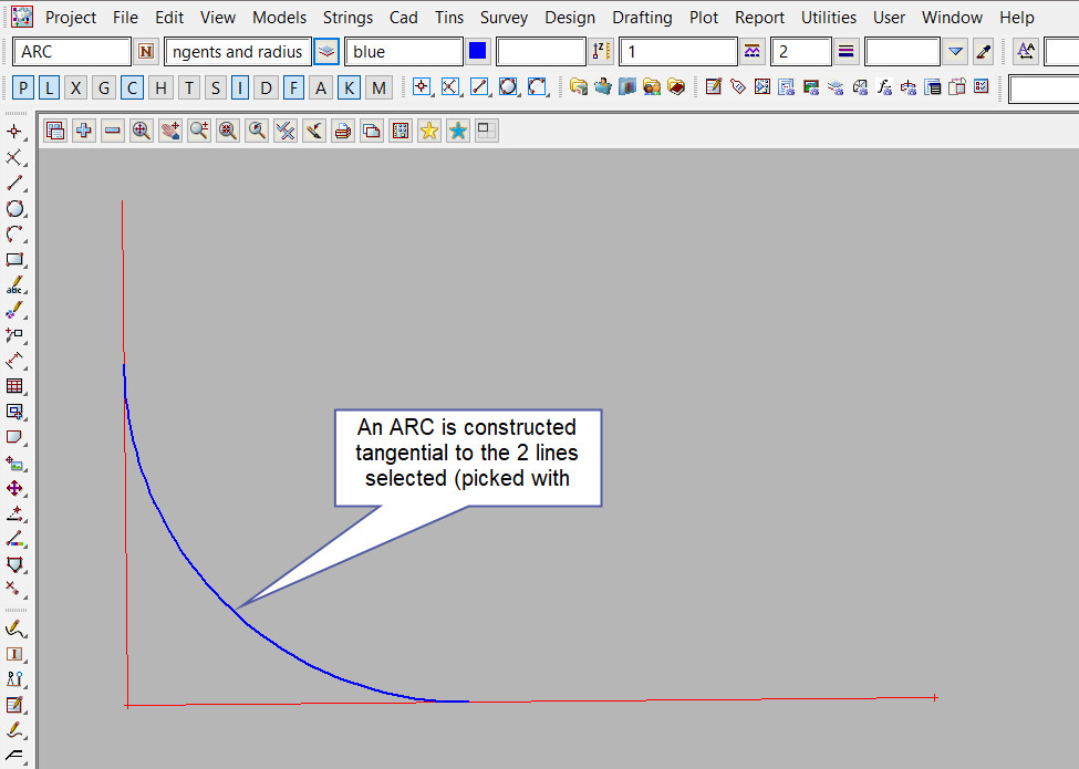
The new arc is created tangential to the 2 selected string segments and to the given radius.
Use a String Inquire to check the details of the new point.
