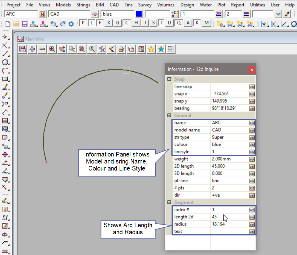
This tool is used to create a CAD Arc, using 2 points and arc length.
The video below will show how to create a CAD Arc using the 2 points and arc length method.
Or continue down the page to see the CAD Arc 2 points and arc length create option.
This CAD Arc 2 Points and Arc Length option is found on the CAD Arc Toolbar, and is the 7th option when the toolbar files out.
Or from the menu, Use: CAD => Arc => 2 Points and Arc Length
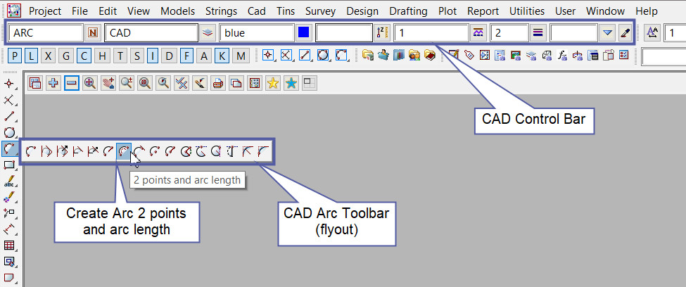
CAD Control Bar Options
The Point is created and placed using the details from the CAD Control Bar, these include,
String Name, Model, Colour, Z – Value, Linestyle, Weight and Tinable.
If you would like to learn more about the CAD Control Bar and how to utilise it,
Visit this post: CAD Control Bar – How to Utilise It
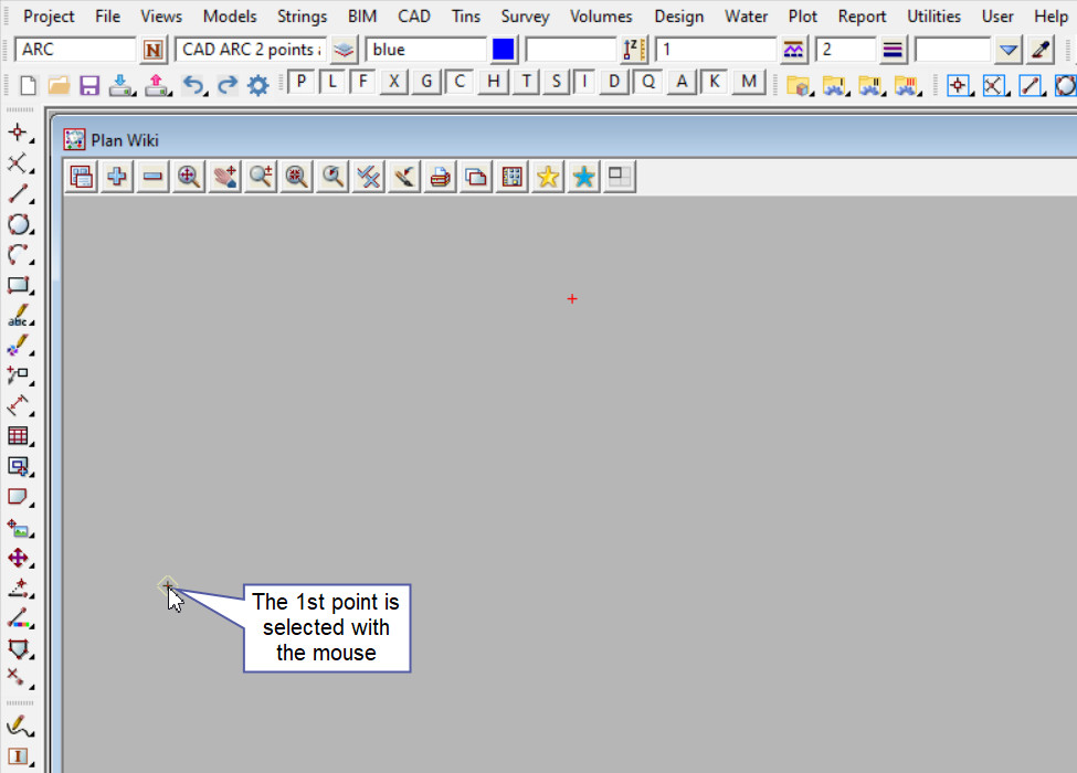
The 1st point is selected with the mouse or entered in via the keyboard. To specify the 1st point with the mouse, a point must be selected (Left Button) and accepted (Middle Button).
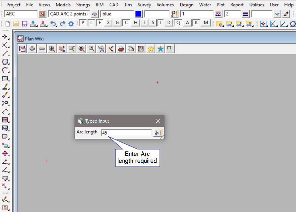
The next step required is for you to enter the Arc length required, type a number into the box and press enter.
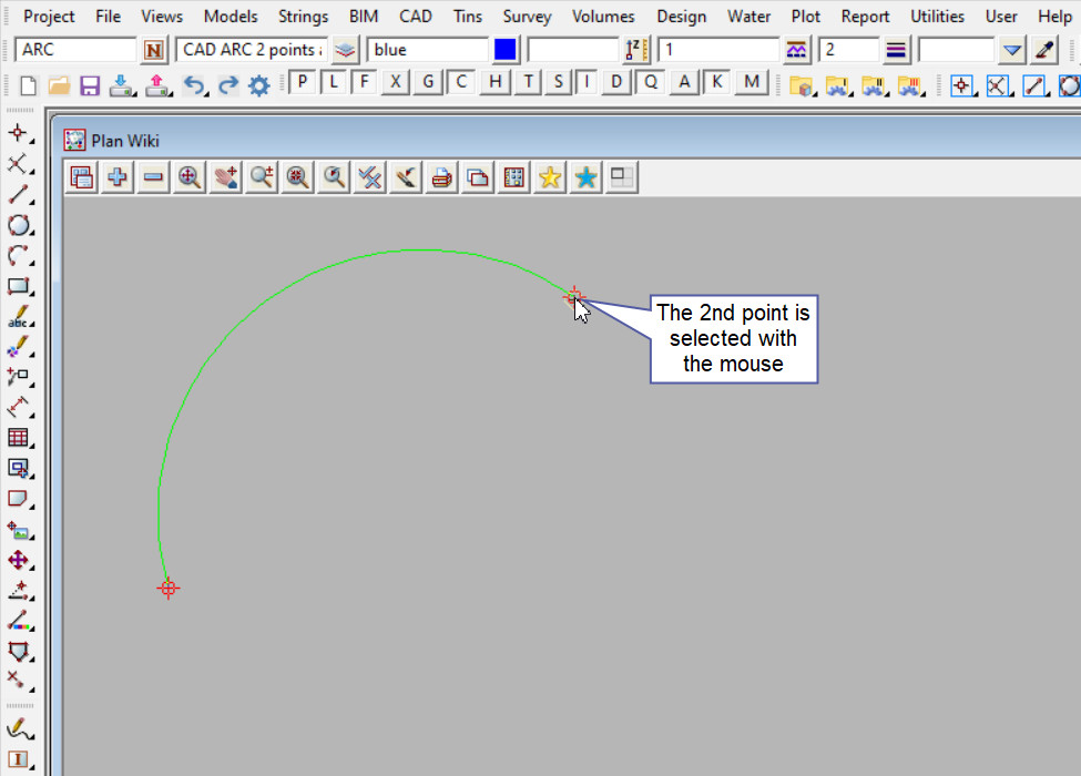
The 2nd point is selected with the mouse or entered in via the keyboard. To specify the 2nd point with the mouse, a point must be selected (Left Button) and accepted (Middle Button).
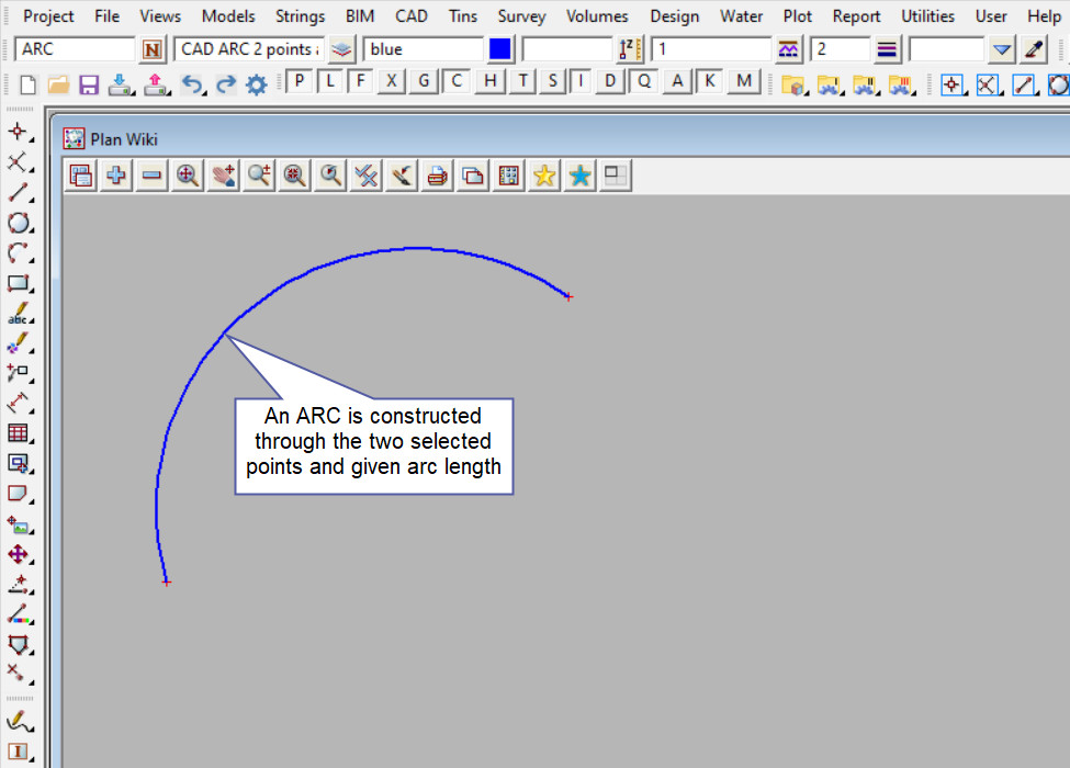
An arc is constructed through the two selected points and the given arc length.
Use a String Inquire <F2> to check the Arc details.
