This tool is used to create a CAD Point.
The video below will show how to create a CAD Point using a Cursor location or apply typed coordinates.
Or continue down the page to see the CAD Point create options.
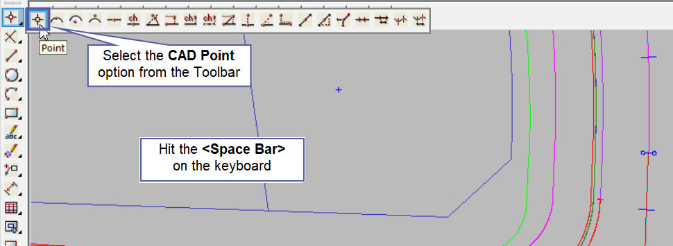
The CAD Point option is found on the CAD Point Toolbar, and is the first option when the toolbar flies out.
Or from the menu, Use: CAD => Point => Point
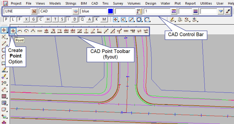
CAD Control Bar Options
The Point is created and placed using the details from the CAD Control Bar, these include, String Name, Model, Colour, Z – Value, Linestyle, Weight and Tinable.
If you would like to learn more about the CAD Control Bar and how to utilise it,
visit this post: CAD Control Bar – How to Utilise It
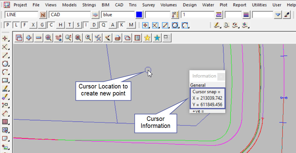
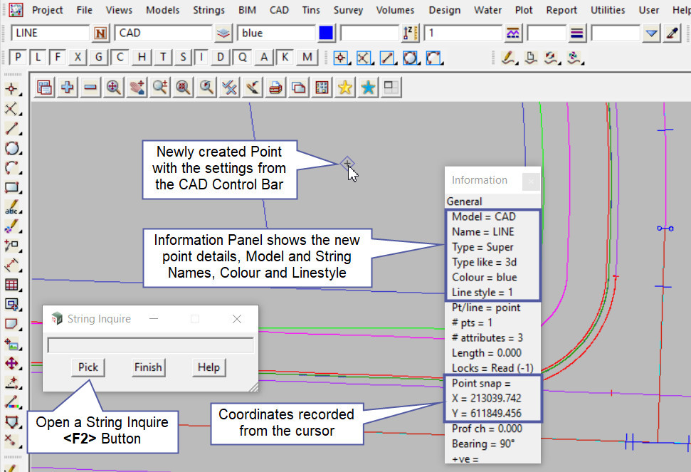
To create a point on the screen, pick a Cursor location and the information panel is shown. Accept the cursor location to create the new point.
Note: Turn the model onto the screen if the point is not shown.
Use a String Inquire to check the details of the new point.
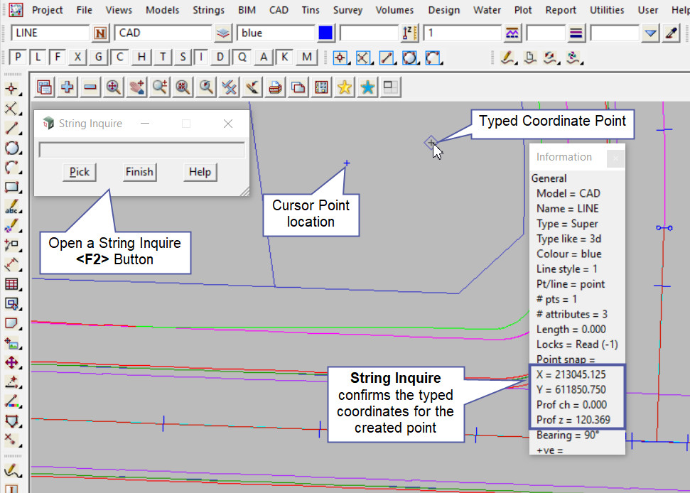
To create a Point at a known coordinate, select the Point option on the CAD Point Toolbar

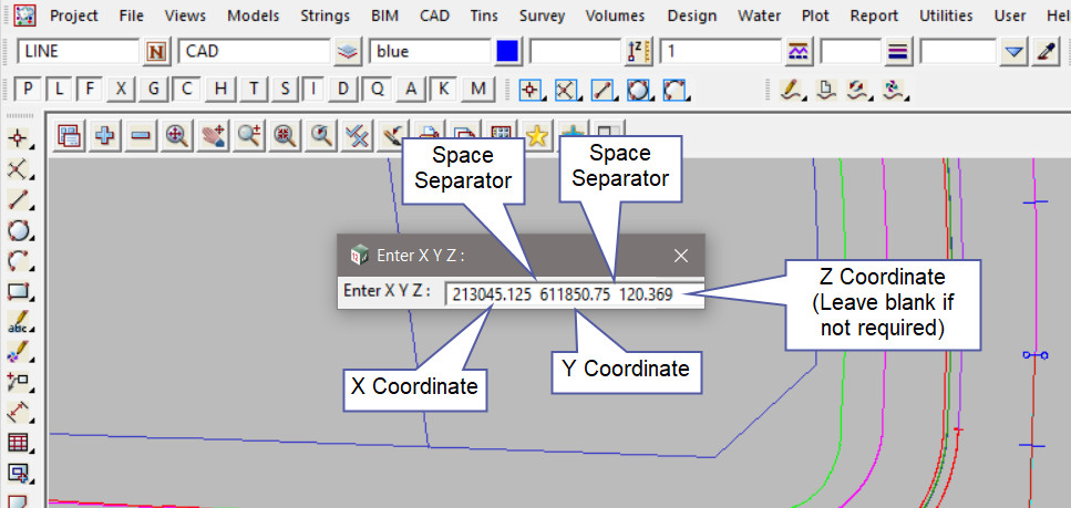
Once the Toolbar option has been selected, hit the <Space Bar> on the Keyboard and a Typed Input panel will appear:
Type in the coordinates required:
213045.125 611850.75 120.369
X Coord Y Coord Z Coord (If not required leave blank)
The coordinates need to be entered into the panel and separated by a space.
Once the coordinates are entered into the panel, hit the <Enter> key on the keyboard to create the point. Use a String Inquire to check the point details.
