This tool is used to create a CAD Point by an Offset Intersection, located at the intersection of two offset segments, either line or arc segments.
The video below will show how to create a CAD Intersection of two offset segments.
Or continue down the page to see the CAD Intersection Two Offset Segments create options.
This CAD Intersect 2 Offset Segments option is found on the CAD Intersection Toolbar, and is the 2nd option when the toolbar files out.
Or from the menu, Use: CAD => Intersection => 2 Offset Segments
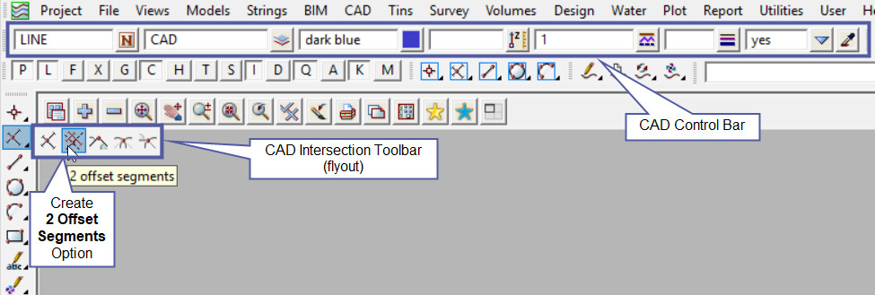
CAD Control Bar Options
The Point is created and placed using the details from the CAD Control Bar, these include,
String Name, Model, Colour, Z – Value, Linestyle, Weight and Tinable.
If you would like to learn more about the CAD Control Bar and how to utilise it,
Visit this post: CAD Control Bar – How to Utilise It
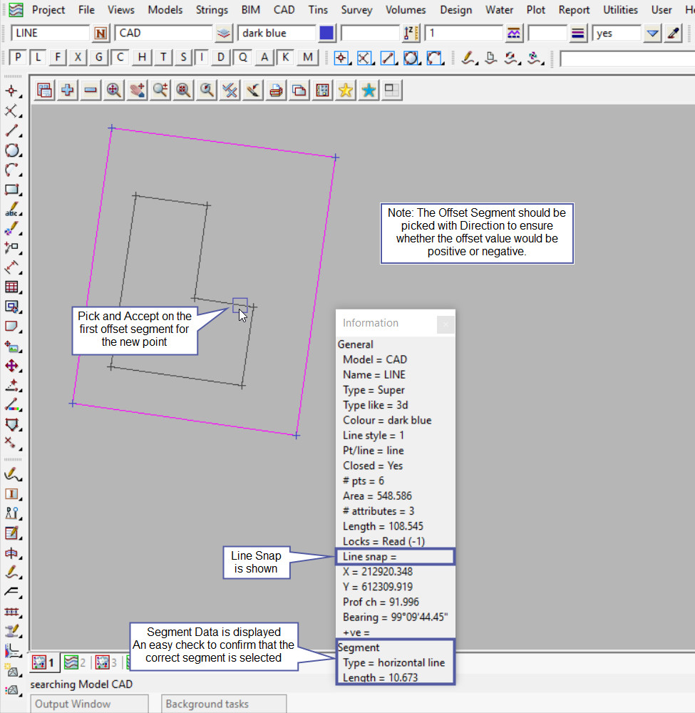
To create a point at the intersection of 2 offset segments, initially select the first segment for the intersection with pick with direction.
The information panel will show that you have selected a line snap. Then accept the segment.
If you would like to learn more about Picking with Direction and how to utilise it,
Visit this post: Picking with Direction
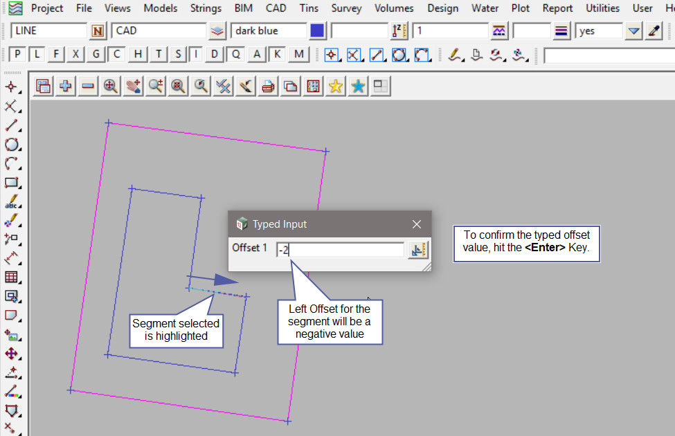
The first segment is highlighted and the Typed Input Panel has opened to enter the first offset.
Note: Remember that a positive offset is to the right and a negative offset is to the left.
If you would like to learn more about the Typed Input Panel and how to utilise it,
Visit this post: Typed Input Panel
There is now a construction line showing the -2m offset from the first selected segment.
Pick with direction the second segment to offset, and accept the segment.
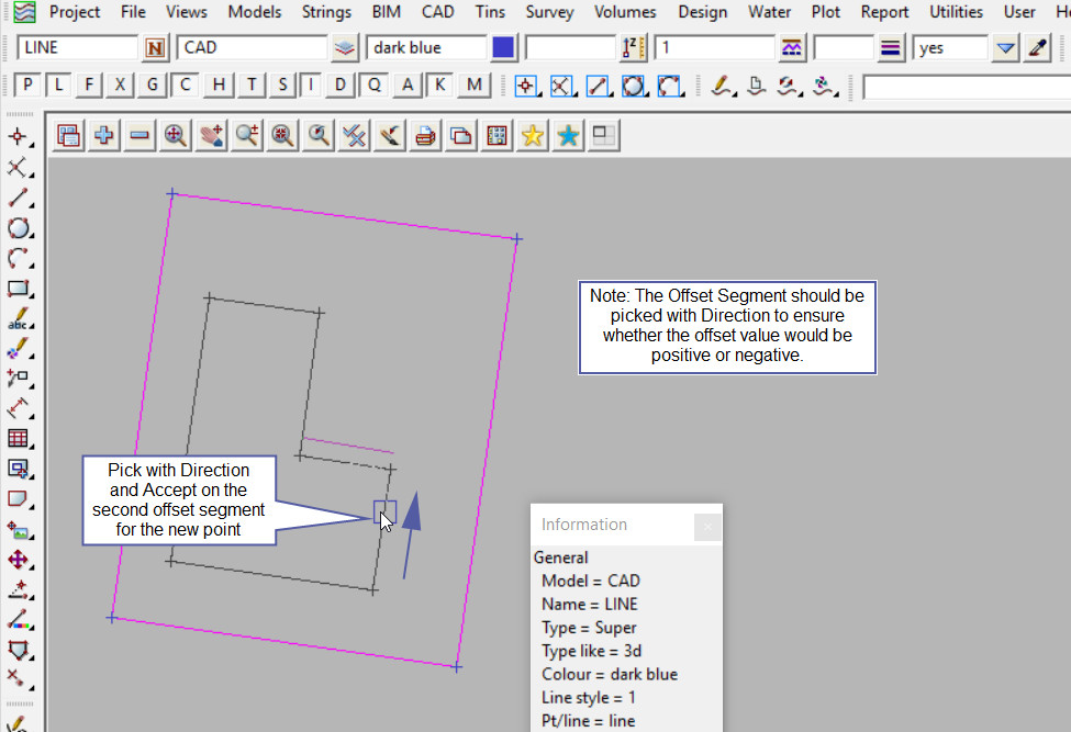
After the segment is accepted, enter the offset value for the intersection point to be created. For this example we will use a zero (0) offset to line the new point up with the edge of the house.
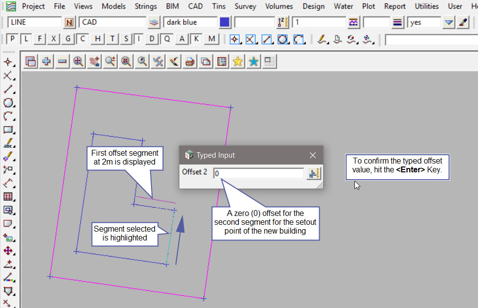
After the second offset has been entered and the <Enter> key has been hit, the new intersection point will appear on the screen.
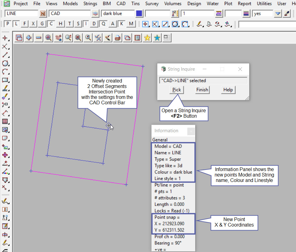
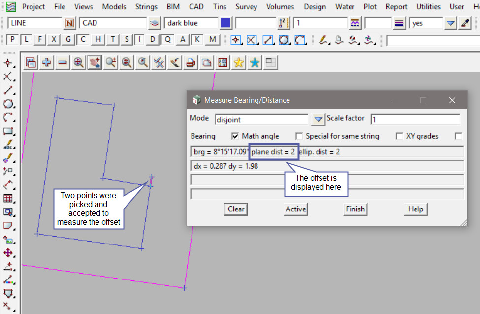
Use the Measure Bearing/Distance option to check the newly created point.
If you would like to learn more about the Measure Bearing/Distance option and how to utilise it,
Visit this post: Measure Bearing/Distance
