This option is used to set many different Tin Render settings for detailing a Tin in the project.
Continue down the page to see the Tin Render Settings Panel options.
To view the Tin Render Settings Panel, Use: Tins => Edit => Tin Render Settings
The Tin Render Settings Panel can also be found under: BIM => Visualisation => Tin Render Settings

Tin Render Setting Panel Details
For a tin added to a Perspective OpenGL view with Shade toggled on, the triangles of the tin can be displayed as a solid colour or be transparent depending on the Blending value which can vary between 1 and 0.
A tin can be one sided and only viewable from above, or two sided and viewable from above or below.
Rasters, such as photos, can also be associated/draped onto a tin and viewed in a Perspective OpenGL view with the shade toggled on.
For triangles that are not the base tin colour, textures can be applied to the triangle using a Texture mapping file.
Finally text, filled polygons, text, billboards and images in models added to any Perspective OpenGL view that the tin is on can also be attributed so that they can be draped and displayed on the tin.
IMPORTANT NOTE: the Visualisation module is required for the Tin Render Settings to be used on a Perspective OpenGL view.
Blending the Tin
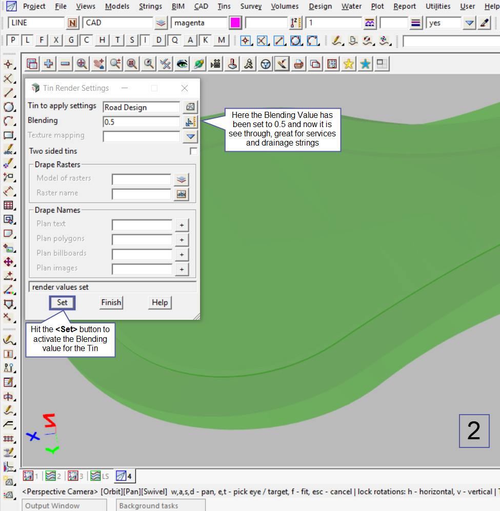
The default Blending value for a tin shown in an OpenGL Perspective view is a value of 1, this means that the tin is shown as a solid colour. The tin can have a blending value from ‘1 to 0’, where ‘0’ (zero) means the triangles are totally transparent, so the tin cannot be seen at all.
Setting a Blending value of 0.5 as shown in the 2nd image below means that it become semi transparent, allowing other data or tins to be seen through it.
Applying Textures to the Tin
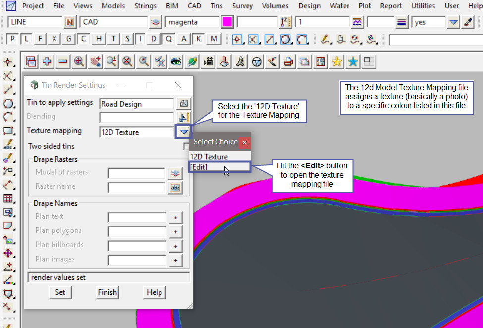
Select the ’12D Texture’ Mapping file from the drop down menu. Textures in 12d are basically a photo of a surface/texture and saved into the file to be draped onto a tin surface, based on the colour of the triangles.
Hit the <Edit> button from the drop down menu to open the ’12D Texture’ file.

Once the ’12D Texture’ file is opened the two columns show that the 12d Colour is assigned a Texture name, the texture name is then reference from the textures.4d file. The file references an image of the texture and is applied to the triangles of that colour in the tin.
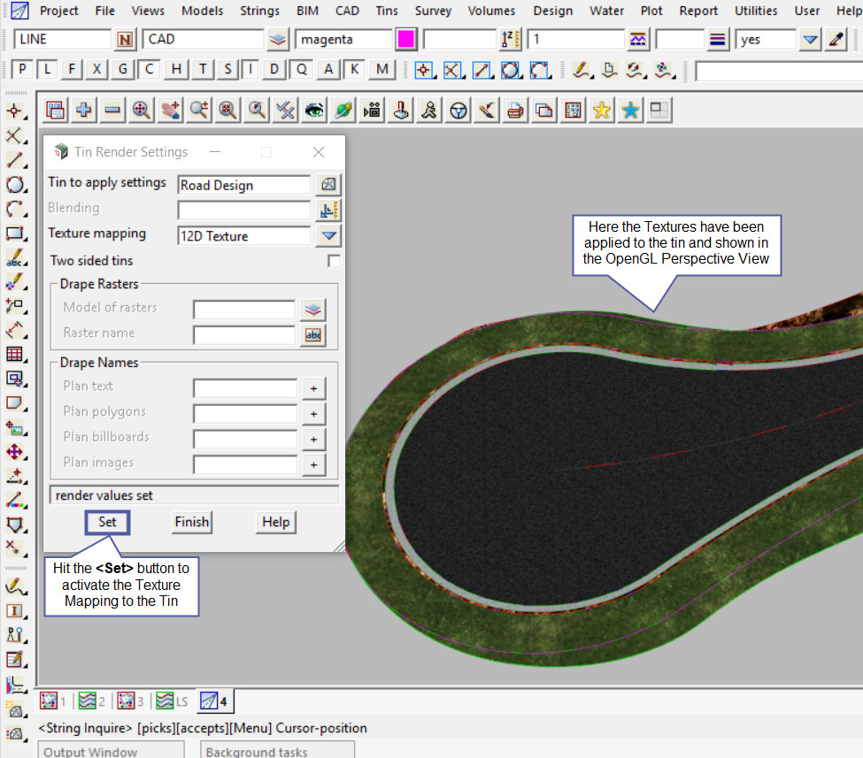
Hit the <Set> button to apply the texture mapping to the tin.
Once the Texture Mapping file is loaded into the panel, hit the <Set> button to apply the Texture Mapping to the Tin.
The Textures have been applied to the Tin and will be displayed on the Perspective OpenGL view.

Applying a Raster Image to the Tin
To apply a Raster Image to a tin, this means that the aerial image will be transposed onto the Tin. The Raster Image has to already been imported into the project.
If you would like to learn more about importing Raster Images into a 12d Project,
Visit this post: Import a Raster Image
Below the image displays the tin and raster models on the plan view and that they are in the same location. Then the perspective view is displaying the tin in 3D, but the raster image has not been associated with the tin (transposed).

Open the Tin Render Settings panel if it is not already open, Tins => Edit => Tin Render Settings
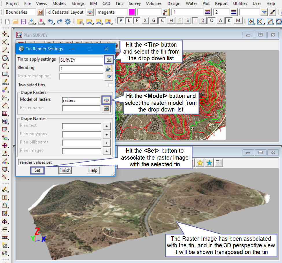
Hit the <Tin> button and select the tin from the drop down list.
Hit the <Model> button and select the Raster model from the drop down list.
Hit the <Set> button to associate the raster image with the selected tin.
Now in a 3D perspective view the tin will be shown with the raster image transposed onto it as shown below.
Note: To view the raster image on the tin in a 3D perspective view, the Visualisation module is required. Without the Visualisation module this option will not work.


