Excess Flow – Hydraulics for the Rational Method
During your Rational Analysis you may get a message that looks like this:
WARNING HGL cannot reach grate, Qx routing disabled at this pit.
1-6 Grate level is 0.091 above lowest upstream grate level. Route from min grate level is: 6-1
1-3 Grate level is 0.327 above lowest upstream grate level. Route from min grate level is: 7-1
2-2 Grate level is 0.088 above lowest upstream grate level. Route from min grate level is: 3-1
This might need action to fix an issue, and it might not, the fastest way to tell is to look at a longsection of the water string.
If the HGL is near the surface, then you need to take action, but if the water level is low and there is a lot of freeboard, then no action is required.
Qx is ‘Excess Flow’. It is water that cannot enter the node because the node is already full of water.
The node is full of water because the pipe that takes the water away is too small or too flat.
If there is ‘Excess Flow’ and there is a Bypass Route away from the node, then 12d will usually ‘Route’ the flow from the pipe, and send it to the bypass route.
This is what would happen in real life: The amount of water entering the node would be reduced, the amount of water in the bypass route would increase.
The node could even surcharge if incoming pipe flows were high.
But there are some situations where this will not happen….see below.
If there is ‘Excess Flow’ and there is a Bypass Route but Qx Routing is disabled, then 12d Model cannot send the water to the overland flow route, the rating curve for the node will be used to determine how much water is captured at the node and all discharge from the node will be through the downstream pipe.
You will get a message about ‘all water forced into pipe’ – see below.
If there is ‘Excess Flow’ and there is no overland flow route, then there is no place for 12d Model to send the water, and all of the approach flow will be captured at the node and sent through the downstream pipe.
You will get a message about ‘all water forced into pipe’ – see below.
PROBLEM: Pipe “1-6” to “1-7” – US pit HGL of pipe reached the network minimum upstream grate level(see Qx messages above for location). Unable to re-route excess pipe flow (Qx) of 0.1017 cumecs in pipe … All flow forced into pipe and the US pit and pipe hgls will be greater than that reported.
This message means:
- The water level reached the grate (either at the node, or an an upstream node)
- 12d Model had nowhere to send the water (there is no overland flow route, or Qx Routing for the node is disabled)
- So all the water was forced through the pipe – even though the pipe could not really carry that amount of water
- An HGL will be displayed on the longsection, but don’t believe it.
Most of the time when you have an overland flow route everything works just fine.
If the discharge pipe is too small then the water is routed to the bypass route, and flow in the overland flow channel will increase just as it would in real life.
Qx Routing is disabled if:
- The Qx Routing increment is set to zero, or
- The ‘Consider Bypass Flows’ tickbox is unticked,
(it’s in the top right corner of the ‘Analysis’ panel), or - There is a grate upstream that is lower than the grate at the node being considered.
Item 1 and 2 are easy to understand and fix.
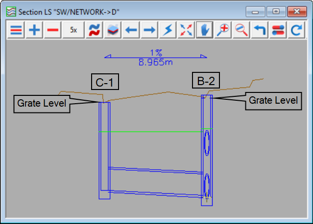
For item 3, consider the screenshot below.
Pit B-2 is not going to surcharge because the water would come out at C-1 first.
Qx Routing is disabled at B-2 because the grate at C-1 is lower than the grate at B-2.
Note that Qx Routing is only disabled at B-2
(C-1 is fine. It’s just causing the issue at B-2).
In my case Qx routing from B-2 has been disabled, and 12d has told me that it has been disabled, but I don’t care.
The discharge pipe (taking water away from B-2) is big enough, the water level in B-2 is low, there is no Qx and no problem.

Fixing ‘Qx Routing disabled’ – Item 3
In the screenshot above Qx Routing is disabled because the Grate at C-1 is lower than the Grate at B-2
The easy fix is to go to the Node tab on the Water Network Editor and manually set the Grate at C-1 to be 1mm higher than the Grate at B-2.
For On-grade nodes this will have no effect on inlet capacity. Catchment flows and incoming bypass flows arrive at the Grate.
For Sag nodes the maximum depth of ponding is calculated by 12d Model, and depends on the Grate level.
So for Sag nodes you will need to manually set the maximum depth of ponding.