This option is used to calculate heights at points of an existing Tin, and be added to a
set of grid strings over the tin.
Continue down the page to see the Grid DTM Panel options.
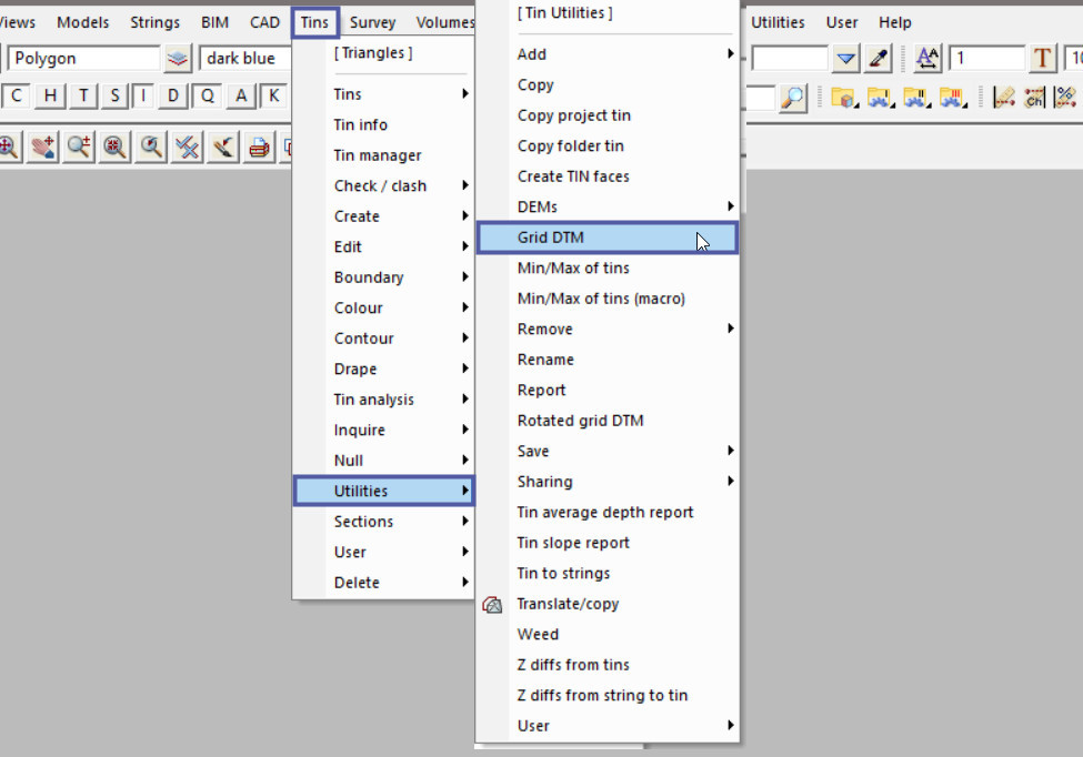
To view the Grid DTM Panel, Use: Tins => Utilities => Grid DTM

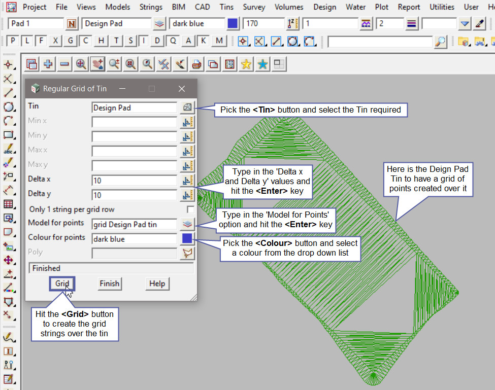
Pick the <Tin> button and select the tin required.
The Minimum and Maximum x and y are optional, if left blank the whole tin will have a grid created over it. If only a certain grid area of the tin is required then use these options to restrict the grid creation.
The ‘Delta x’ and ‘Delta y’ options will determine the distance between the points when the grid is created.
Type in the ‘Model for Points’ name and hit the <Enter> key.
Pick the <Colour> button and select the colour from the drop down list.
The ‘Poly’ option allows the creation of the grid to be restricted to within a polygon. If no polygon is selected the grid will be created over the whole tin.
Hit the <Grid> button to create the grid strings over the tin.

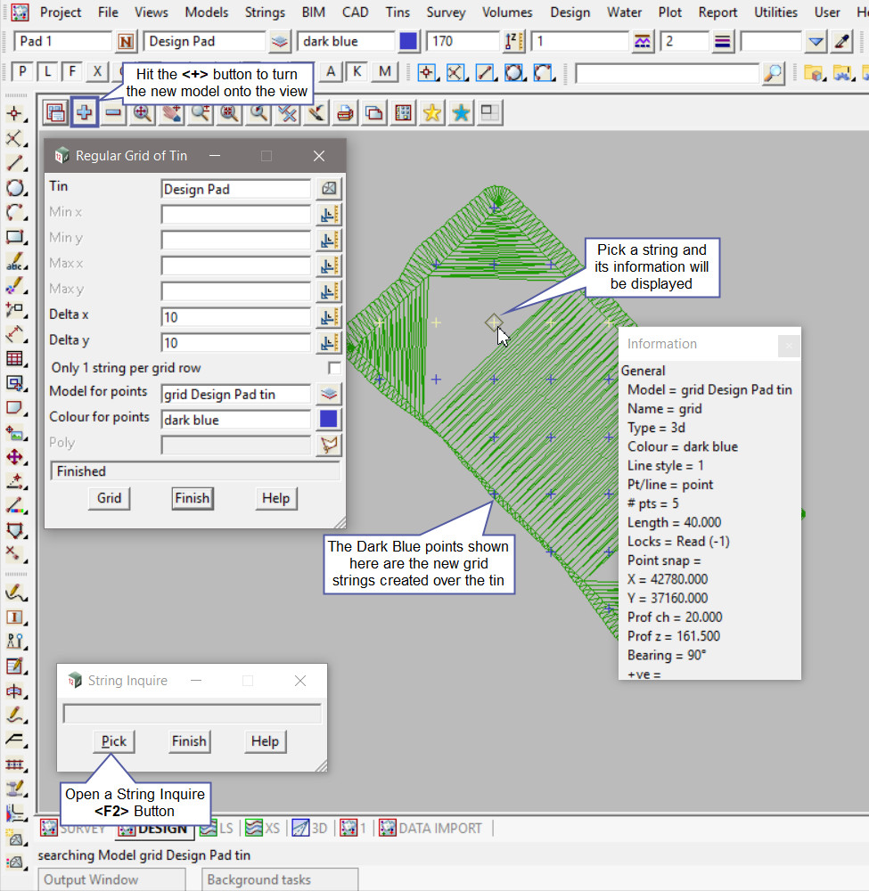
Hit the <+> button to turn the new grid model onto the view. The new ‘grid Design Pad tin’ model has been added to the view. The contents of the model are the dark blue strings (points) sitting over the tin.
Use a String Inquire to check the details of the new grid strings.

In this example the ‘Vertex Indices’ have been toggled onto the view (to show the point crosses) and the size and colour have been adjusted to be seen on the view.
If you would like to learn more about the Toggle button and the options available,
Visit this post: View Toggle Options