This tool is used to create a CAD Arc, using start point radius chord length and bearing.
The video below will show how to create a CAD Arc using the start point radius chord length and bearing method .
Or continue down the page to see the CAD Arc start point radius chord length and bearing create option.
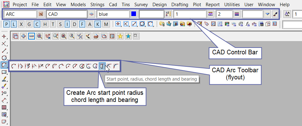
This CAD Arc Start Point Radius Chord Length and Bearing option is found on the CAD Arc Toolbar, and is the 14th option when the toolbar files out.
Or from the menu, Use: CAD => Arc => Start Point Radius Chord Length and Bearing

CAD Control Bar Options
The Point is created and placed using the details from the CAD Control Bar, these include,
String Name, Model, Colour, Z – Value, Linestyle, Weight and Tinable.
If you would like to learn more about the CAD Control Bar and how to utilise it,
Visit this post: CAD Control Bar – How to Utilise It
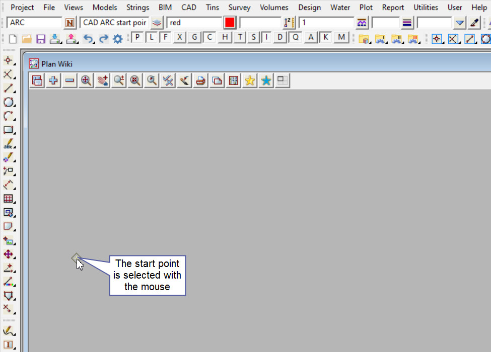
The start point of the arc is selected with the mouse or entered in via the keyboard. To specify the 1st point with the mouse, a point must be selected (Left Button) and accepted (Middle Button).

The next step required is for you to enter the Radius of the Arc, type a number into the box and hit the <Enter> key.
Note: Arc and Circles in 12d Model can be both clockwise and anti-clockwise in direction.
Clockwise arc/circles are entered into a panel with a positive (+) radius.
Anti-Clockwise arc/circles are entered into a panel with a negative (-) radius.

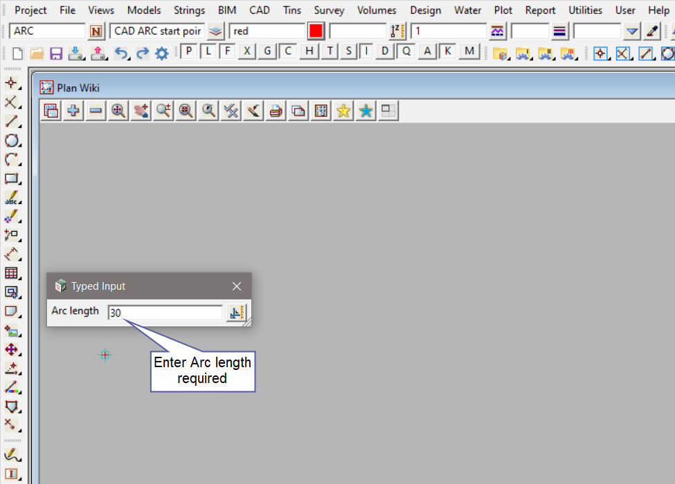
The next step required is for you to enter length of the Arc, type a number into the box and hit the <Enter> key.

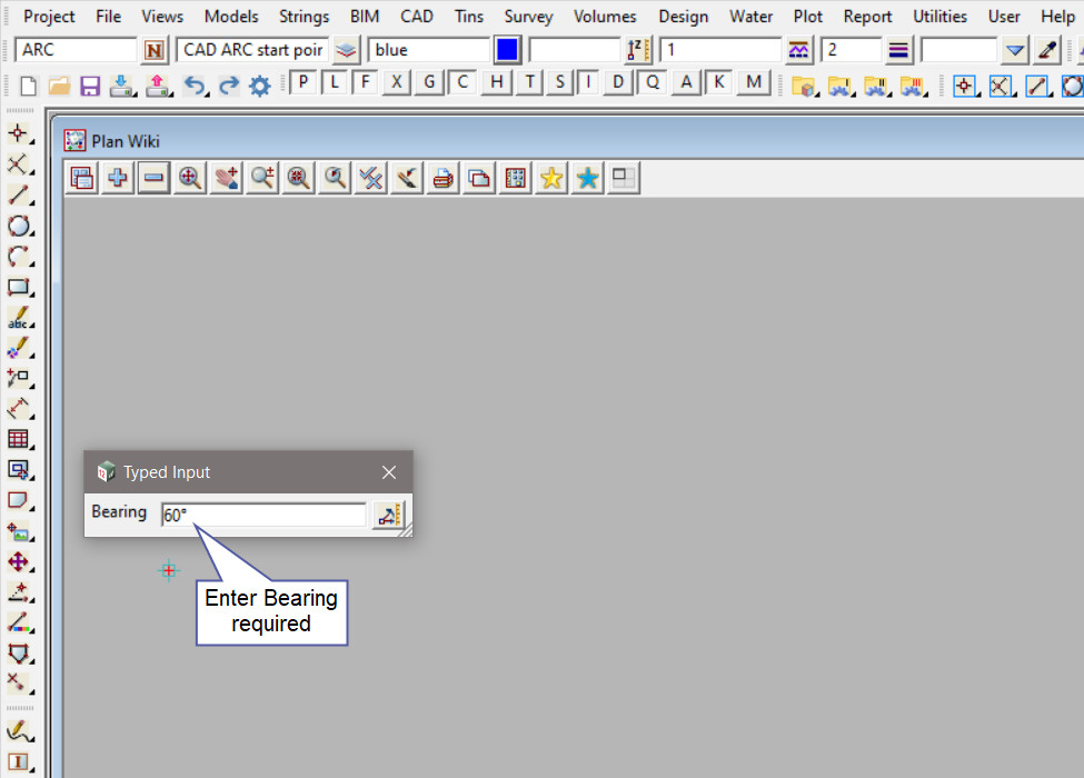
The final step required is for you to enter a bearing, type a number into the box and hit the <Enter> key. The start point of the arc will be tangential to the bearing angle entered.

An ARC is constructed using the information entered.

Use a String Inquire <F2> to check the Arc details.
